Shocking Results
The Shock Absorber Theory
On-road or off, your shock absorbers control how your ride feels and behaves while in the dunes or on track pulling high-g’s. For this first article, we’ll look at the basic idea of shocks, talk about the twin-tube and mono-tube varieties, and how external shock adjusting works.
The damper is probably better known to most people as a shock absorber or simply a shock. It is a device used to control the rate of pitch and roll of a vehicle. It also controls the rate of motion of a spring inbound (also called bump in racing or jounce in engineering terms) and rebound (also called droop in racing). Without them, your vehicle would just flop around as the springs would have no control and react to not only the road but also itself as it oscillates.
Think of those slow-motion videos of a valvetrain as the cams open and close the valves. Since those valve springs have no dampening control, they bounce and even cause “valve float.” That’s a topic for another day, but just know the same thing could happen in your suspension if you didn’t have shocks.
BASIC DAMPER DESIGN
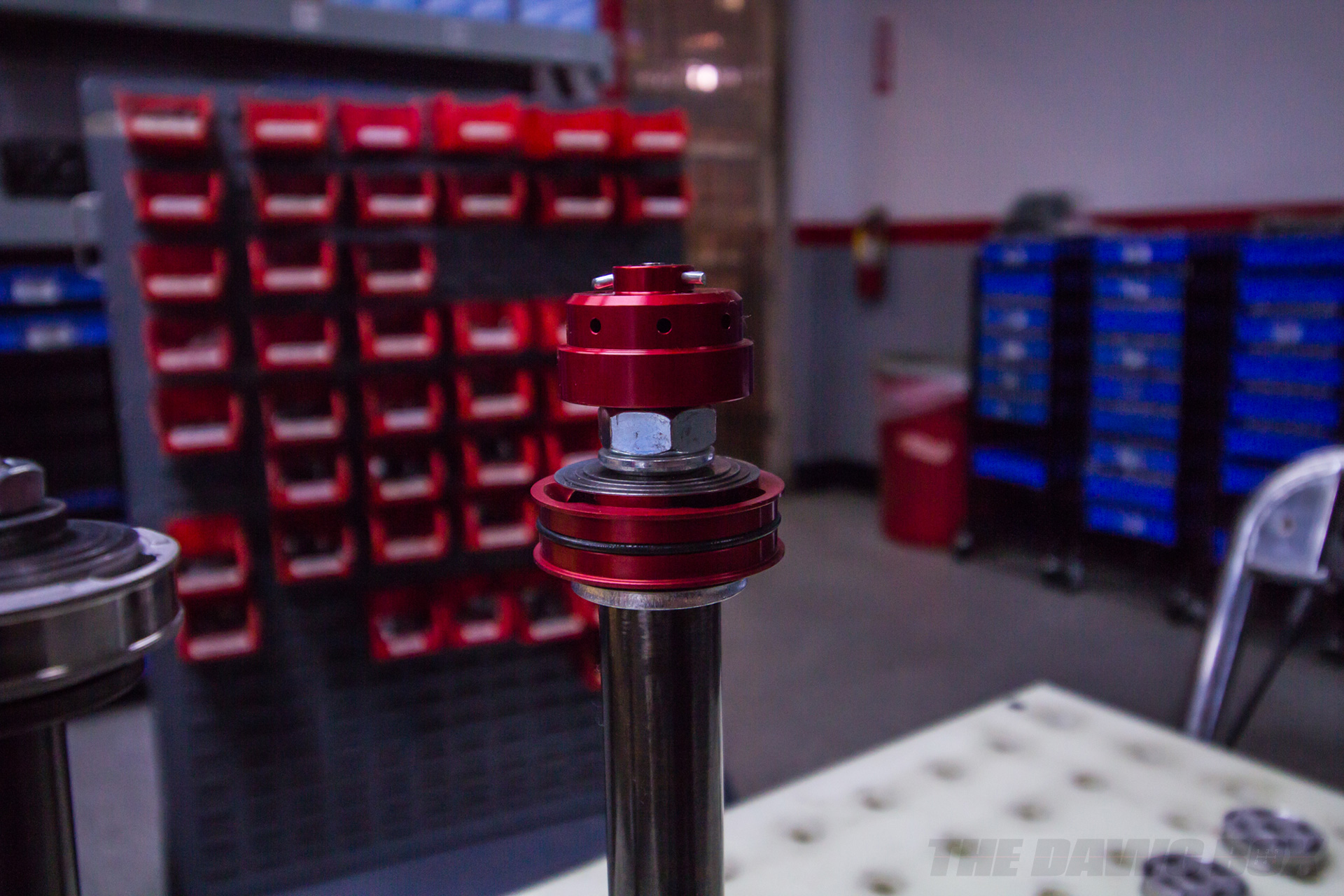
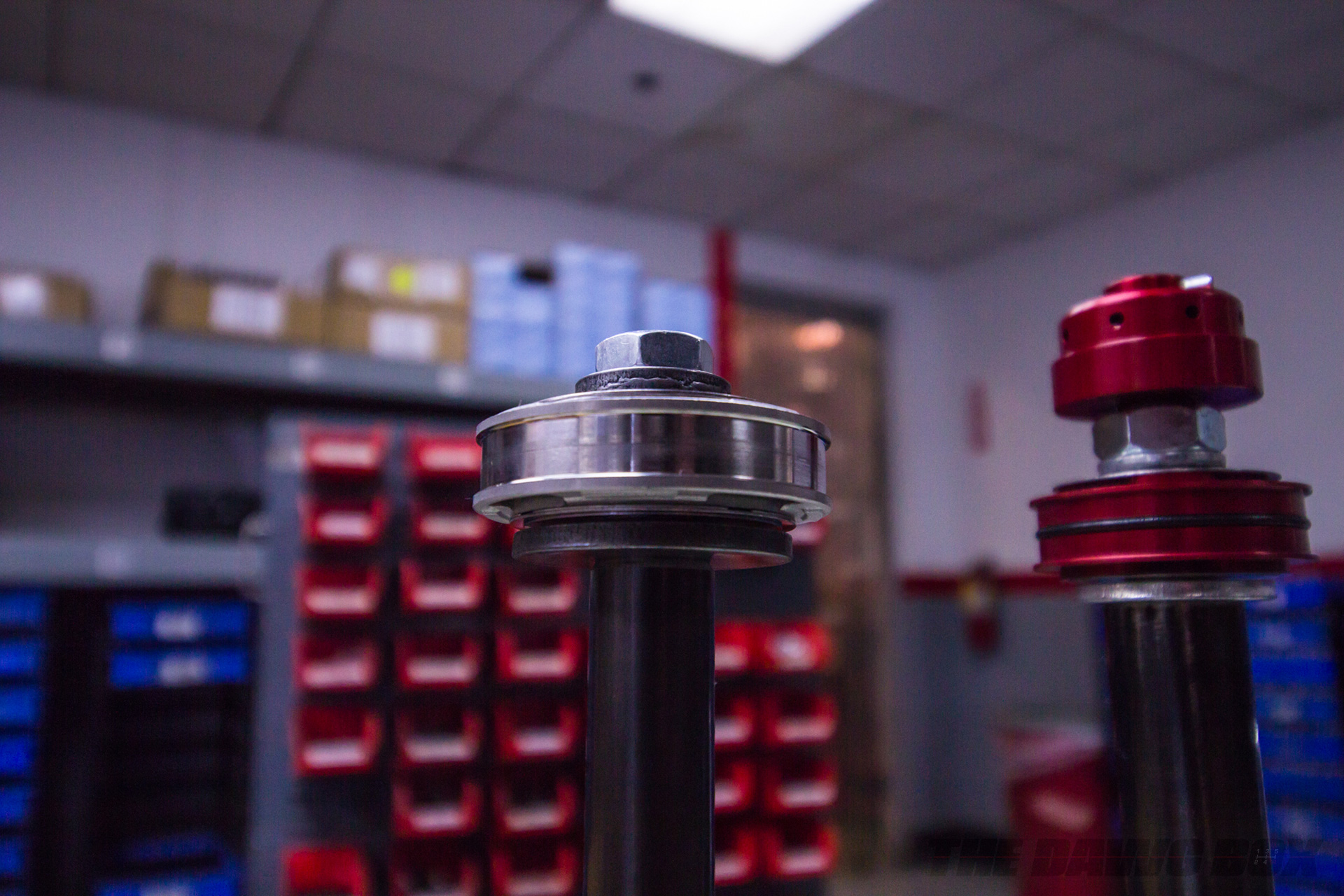
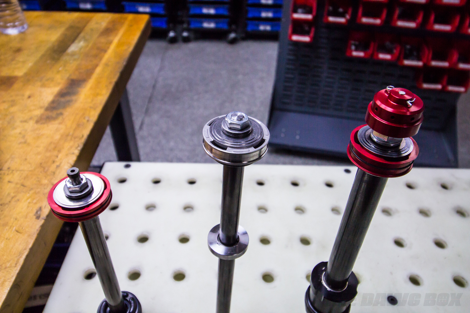
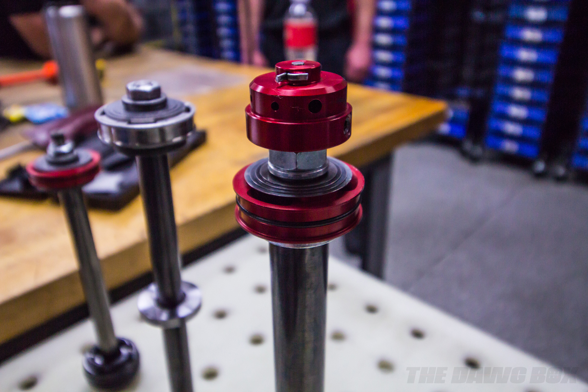
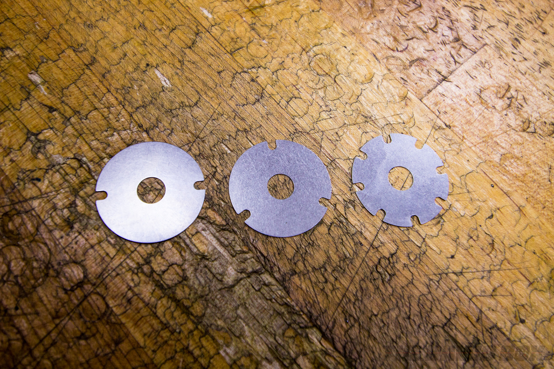
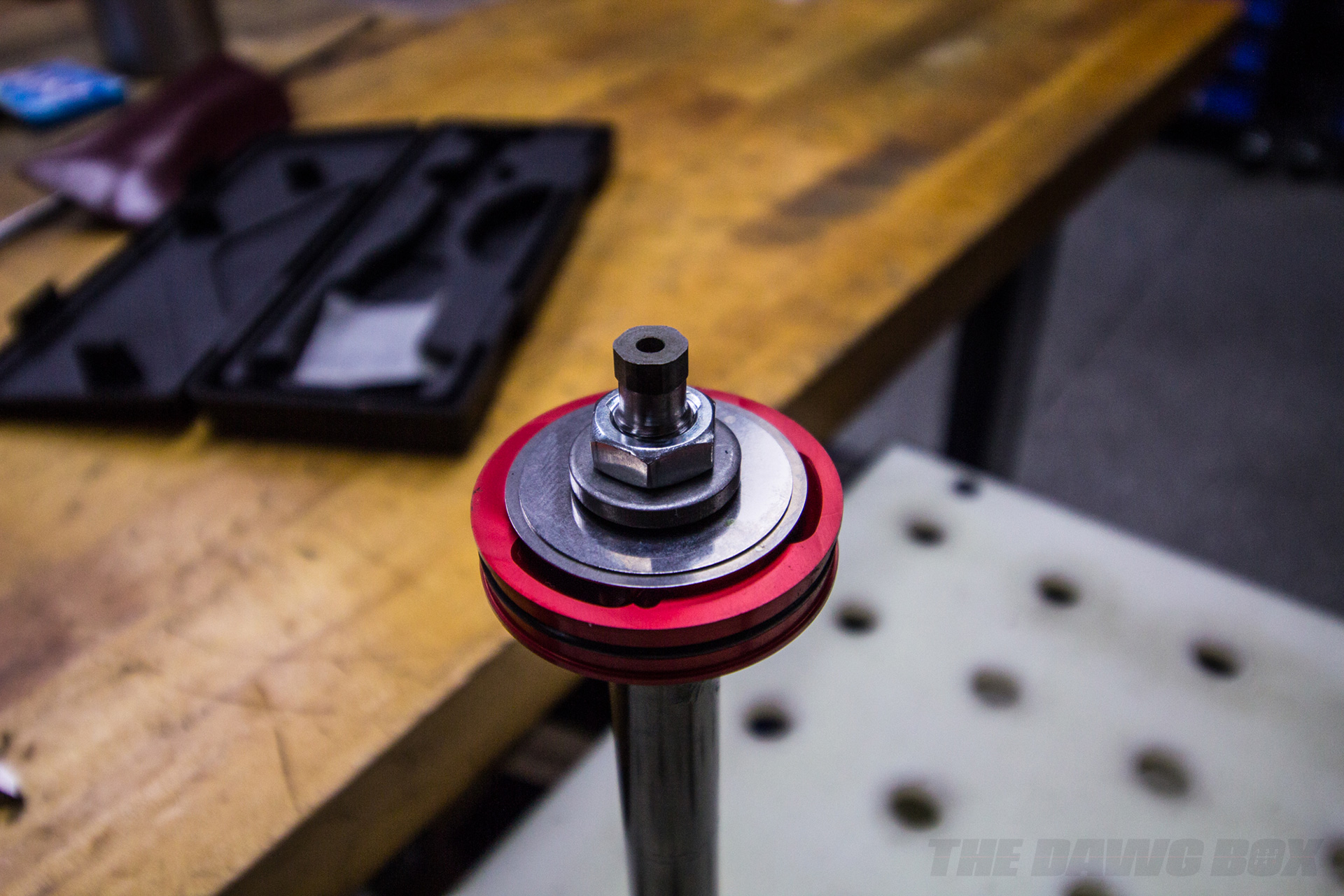
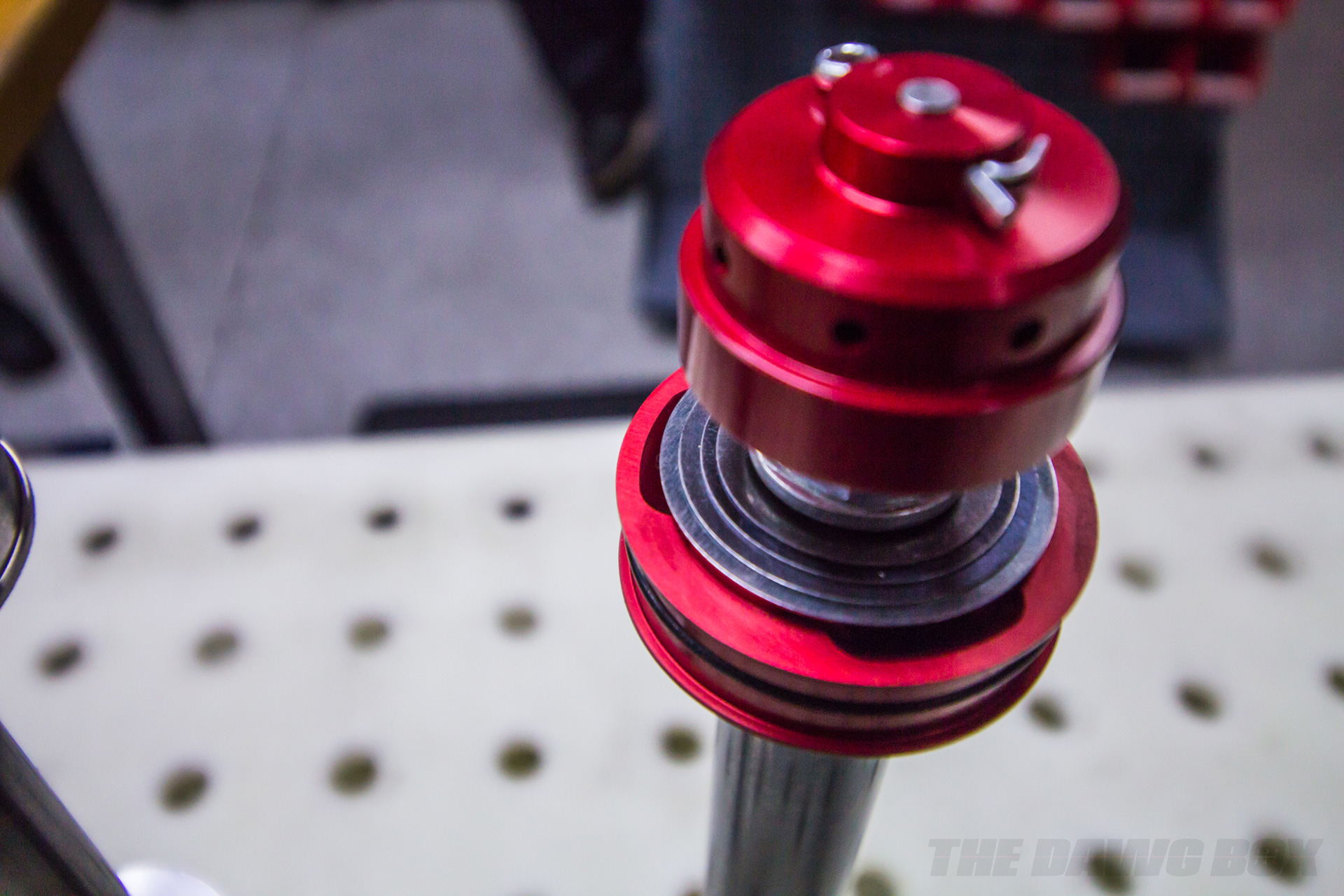
Inside the tubes that make up your shocks is a shaft with a disc connected to the end of it. This is the piston and it has a stack of shims on top of openings cut or molded into the piston. This in combination of flowing through hydraulic oil is how your shocks dampen the springs movements. It sounds simple enough, but there is far more going on than you probably still realize.
THE HOLES AND SHIM STACKS
First, let’s start with the piston design itself. If you’re into RC car racing, you are familiar with how the holes in those pistons control how fast or slow the piston flows through that fluid. The amount and size of those holes partially determine the damping rate. Next are those shim stacks, with a set on top and on the bottom of the piston to further control bound and rebound independently.
The thickness and amount of those shims will further increase or decrease the damping rate on each side of the piston. That’s also why those holes are enlarged and staggered at the face of each side of it. This is so the fluid can flow around the opposite stack, though the piston, and then on to the stack that controls bound or rebound.
DIGRESSIVE AND LINEAR PISTONS IN SHOCK ABSORBERS
The piston face can further control the dampening rate by using a digressive or linear face design. A linear face design is flat and the shim stack acts without any further changes in the reactive speed of the stack. A digressive face piston is dished to allow for preloading of the shim stack to change the dampening rate during slow damper shaft speeds.
To explain shaft speed, think of your vehicle diving down and returning to normal during a stop versus hitting a set of quick bumps in the road. The piston shaft is moving at a slow rate during stopping while it moves quickly during bumps because it’s moving more in a shorter amount of time. That preloading of the stack delays its opening and increases the dampening force during those low shaft speeds. A shock absorber with this type of piston makes it a speed-dependent dampener and a piston can be linear on both sides, digressive on both sides, or digressive and linear on each side. How that’s done is determined by testing on a shock dyno and even driver input for motorsports.
BAD GAS
Now, if you were paying attention in physics class while in high-school or even college if you went, you probably start to see an issue with the piston moving through that fluid. It creates a high-pressure side and a low-pressure side. As the piston moves through the fluid, the “top side” (the side with an inactive shim stack) must force its way through and creates an area of high-pressure. If it was a gas, it would move somewhat freer but wouldn’t act like a good damper.
However, that’s not the issue. The side the piston shim stack is acting on creates a low-pressure side. If you’ve ever boiled water at sea level and at high-altitude, you know that water boils faster at higher altitude because the atmospheric pressure is lower. The exact same thing happens in your dampers.
This is the primary cause of aeration; the shock oil degasses due to low-pressure pulling gas out of solution (also known as vacuum degasification) and even begins to boil the oil on the “bottom side” of the piston as the shock heats up. These gasses cause a feeling of reduced dampening because gas is compressible whereas a fluid is non-compressible.
NON-COMPRESSIBLE FLUID
The fluid being non-compressible is the whole reason a shock works while gas being compressible is the reason why air ride suspensions work. Gasses create a spring force when compressed and are how and why a suspension airbag works in place of a spring. However, you don’t want that in a shock.
You want a fluid that is non-compressible, however, you also want something that will allow the piston to flow through itself but won’t entirely stop it when the rate changes. That’s why a non-Newtonian Fluid like oobleck, for example, wouldn’t work. You could use simple friction and early dampers were designed that way (like the Andre Hartford design), it doesn’t dampen as well as oil does. That’s why a fluid like shock oil has been used in dampers since 1907 and we must give thanks to Maurice Houdaille for its invention.
GOOD GAS
So, how do you prevent the shock absorber fluid from boiling or degassing if it’s our only choice? Simple, by maintaining a constant pressure on both sides of the piston. That doesn’t sound possible, does it. Fortunately, it is by using nitrogen gas to create constant pressure. While you don’t want a gas as your dampening fluid, you do want it to keep the fluid pressure in the damper constant by utilizing its natural spring force.
This natural spring force also allows fluid to react as the piston travels through it. It gives it space while keeping the pressure equal on both sides of the piston. Even though there are holes in the piston, the fluid will still displace until the shims open or it hydrolocks and, just like when your engine does it, that condition can cause catastrophic damage to the damper.
Even so, it is still possible to hydrolock during high shaft speeds and why your vehicle feel like there is a solid block instead of a spring on certain bumps. That can also be solved in piston design with extra holes (like you see on King Racing Off-Road Shocks) or with shim designs that allow fluid to pass (like what’s used by Eibach).
GASSING PRESSURE IN A TWIN-TUBE VS. MONO-TUBE
A twin-tube damper, which uses a tube within a tube design, does mix the nitrogen with the oil, but because it’s at a low-pressure and its molecule is larger than oxygen, so it doesn’t fully mix (or gets dissolved into solution, as they say in science) with the shock oil. It still does, but the amount is small enough to not be an issue for twin-tube dampers. It also has the benefit of being inert, reducing fire risk, and cheaper than other inert gasses as you can pull nitrogen out of the air over argon.
The working cylinder, as the name implies, is where the piston and shock oil work. The outer cylinder, the one you see and touch as you install your dampers, is where the excess oil goes and where the nitrogen lives. A valve between the working cylinder and the outer cylinder allows fluid to flow between them and works as another dampening force control valve.
In a mono-tube design, the body is the working cylinder and that’s it. However, the nitrogen gas is separated by a floating piston that also has a seal to keep the gas contained above that piston. Because of this, the nitrogen doesn’t mix with the shock oil like it does with a twin-tube design. You can typically use the nitrogen gas at much higher pressures because of this separation, as well, which further reduces aeration by degassing and boiling by low-pressure at the piston. A mono-tube also allows for a larger piston – providing more surface area for the oil to work with – and better cooling as the fluid makes direct contact with the cylinder while working and transfers heat away much more effectively.
ADJUSTING DAMPENING FORCE
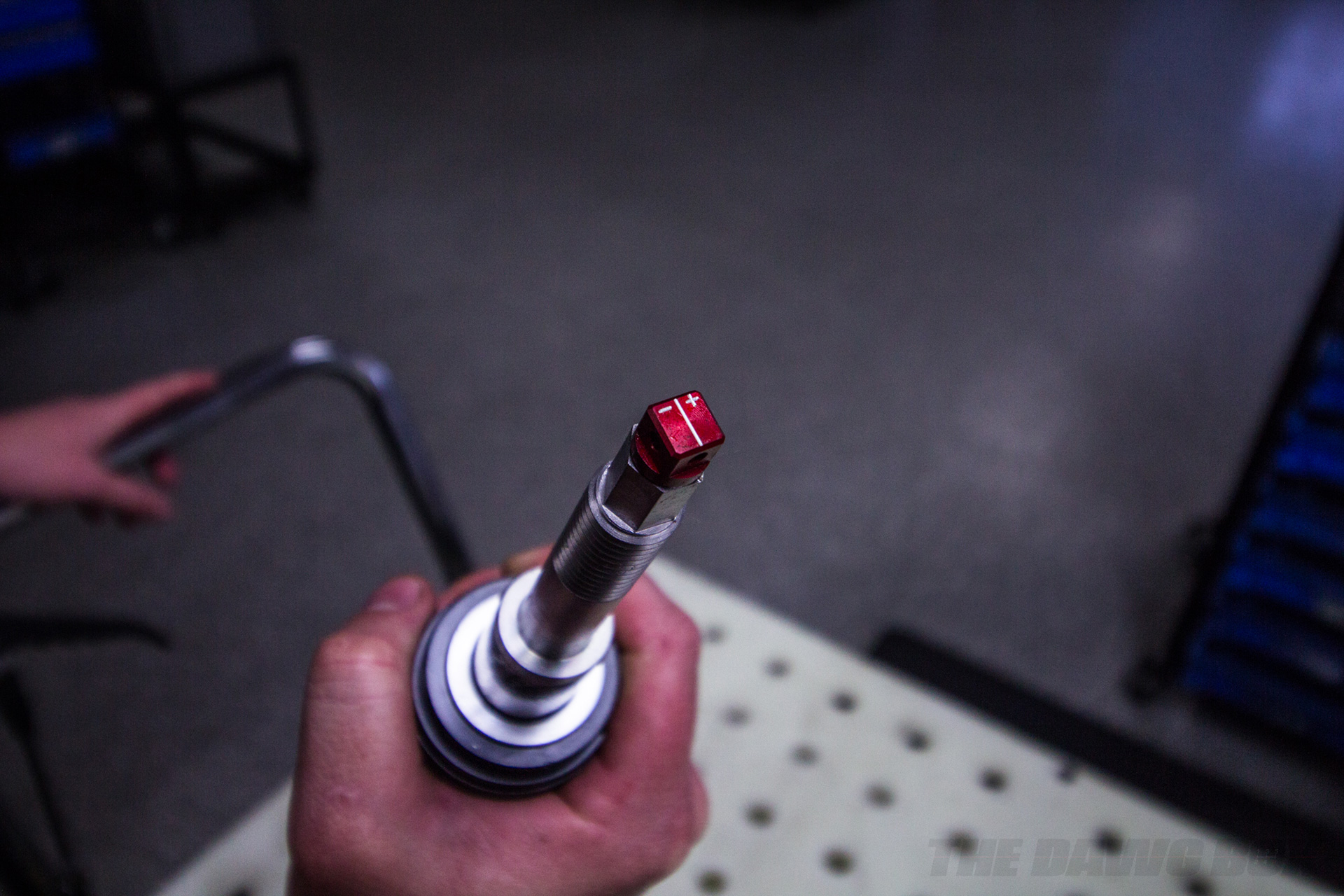
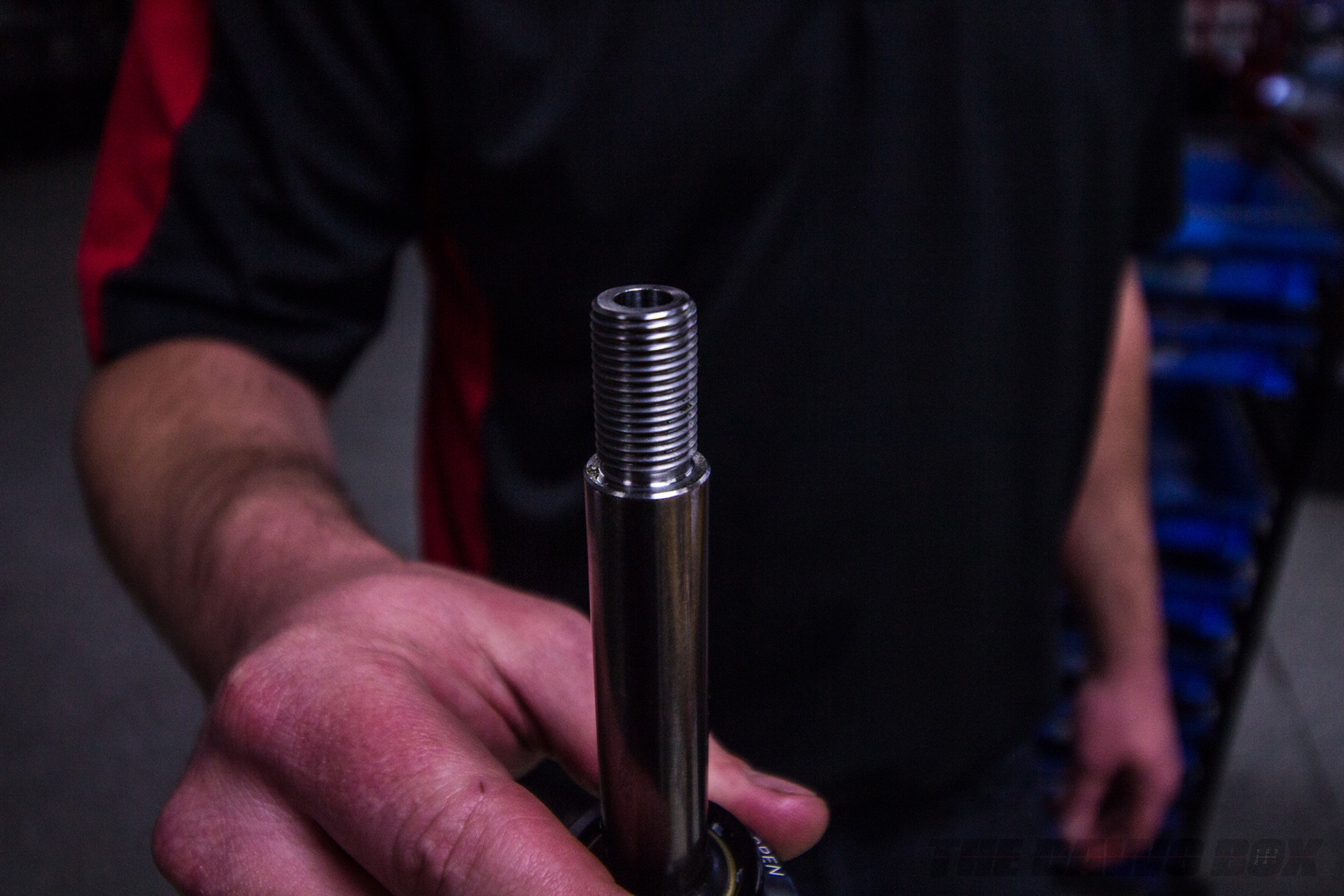
As mentioned earlier, the dampening force is dependent on the piston’s design and the way the shims react as it flows through the shock oil. However, it is also possible to adjust that without tearing apart the damper. The primary way this is done in most mono-tube and several twin-tube damper designs are by allowing the shock oil to bypass the piston. For these Eibach dampers, there are two holes drilled into the damper shaft, one or more above the piston and one through the center of the shaft at the bottom of the piston. The shaft is also drilled through with a rod or needle passing through it.
When the damper uses a rod, it connects to a pod at the bottom of the shaft and a rotating disc that has different sized holes for the oil the flow through. A ball detent not only gives the user an audible “click” to know where they are in their adjustments but also aligns the rotating disc’s holes to the holes of the pod. While simple, this design also limits the adjusting capabilities by only having so many holes to choose from.
In the needle design, the hole goes straight through the damper shaft at the bottom of the piston. Rather than using a rotating pod, a needle limits the opening inside the shaft. It works much like a carburetor needle does by gradually reducing the opening of the orifice. While it does offer far more adjustability, it will eventually full close off the opening, so the adjustment is finite. Another advantage is that the taper of the needle can be modified to change how much and how fast the needle reduces the orifice opening per knob turn before going fully closed.
ADJUSTABLE EXTERNAL RESERVOIRS
External oil reservoirs can also add an additional way to control dampening force by limiting how much fluid flows between it and the damper as it is displaced by the piston. On some shocks with an adjustable reservoir, a ball-detent controlled dial changes the preload the shim stack inside it. This sits on top of what looks like a piston, but instead of flowing through the fluid on a shaft, it’s fixed to the adjuster and fluid flows through it.
Because of this, the nitrogen, along with a floating piston, is in the reservoir rather than the damper body. This still works the same way as it would if it was inside the damper body, the pressure is still maintained by the nitrogen and floating piston. This is also how the twin-tube adjuster works. The base valve between the reservoir cylinder and the working cylinder would work and be adjusted in the same manner.
However, adjustable external reservoir twin-tube dampers do exist. Some don’t have a base valve, and some do but either way, they work very differently from a mono-tube external damper. It does borrow a little bit from the mono-tube external with the nitrogen gas being separated by a floating dividing piston inside the reservoir. Another design is to use a nitrogen bladder over a piston. It’s how the fluid goes from the outer and working cylinders that makes it very different.
What you can’t see is that there are two paths for shock oil to travel. One path is just for bound and is open to the working cylinder while the other is for rebound and is open to the external cylinder. Oil flow control is done by a piston with a spring and rate is controlled by adjusting the preload of that spring. The higher the preload, the more force is required to push the piston open and vice versa. Because of this unique requirement, the reservoir is usually fixed and is part of the damper cap. There are remote external reservoir versions, but these feature two reservoirs rather than a single because the flow must be separated between the two cylinders.


